Updated on: 21 October 2026
An architectural project succeeds or fails based on decisions made at the very beginning. Early alignment between vision, budget, regulations, and technical feasibility determines the strength of everything that follows.
Schematic design plays a critical role in shaping that direction. It transforms abstract ideas into structured concepts that guide the entire architectural design process.
Because decisions made at this stage influence cost, approvals, and coordination, schematic design has a lasting impact on the entire project lifecycle.
This guide explains what schematic design is and how professional bodies define it, what happens in the phase step by step, which drawings and deliverables it produces, how it compares with concept design and design development, how its cost is estimated and how a two-story house moves through it. It ends with the tools architects use and answers to common questions.
What Is Schematic Design?

Schematic design is the first design phase of an architectural project, where the building’s main idea and layout are defined using simple drawings. Architects translate the project brief and client requirements into clear spatial strategies and visual ideas.
At this stage, the focus stays on design intent rather than technical accuracy.
During this phase, architects produce preliminary drawings such as floor plans, basic sections, and elevations. These drawings explain circulation, space relationships, and overall organization. They remain flexible, allowing feedback and iteration before detailed documentation begins.
The purpose of the schematic design phase is to set a clear and shared design direction. Architects test ideas against site conditions, budget limits, and functional needs. As a result, major risks get identified early, and stakeholders gain a common understanding of how the building will work.
The main professional frameworks agree on this role. The American Institute of Architects (AIA) describes schematic design as the first of the architect’s basic services: the architect studies spatial relationships, scale and form with the owner and researches zoning and other limits, and in the AIA’s standard agreement, B101-2017, the phase is followed by design development, construction documents, procurement and construction. The Royal Institute of British Architects (RIBA) calls the matching stage Concept Design, Stage 2 of the RIBA Plan of Work 2020, and the Royal Architectural Institute of Canada (RAIC) covers it in chapter 6.2 of its Canadian Handbook of Practice.
Schematic Design at a Glance
| Schematic design (SD) |
|---|---|
Place in the process | First design phase: after programming and before design development (AIA); Stage 2, Concept Design, in the RIBA Plan of Work |
Main question | What will be built: layout, size, form and a first idea of cost |
Typical drawings | Site plan, schematic floor plans, a few sections and elevations, diagrams and massing models |
Level of detail | Approximate room sizes, often with key and overall dimensions; no construction details |
Cost estimate | Based on area or volume; a Class 4 estimate, typically about −20 % to +30 % |
Approval | The client approves one direction, ideally in writing |
What comes next | Design development (AIA) or Stage 3, Spatial Coordination (RIBA) |
Why Schematic Design Matters
Schematic design is where the biggest decisions are made while they are still cheap to change. Layout, size, form and the rough budget are settled here, so conflicts with the site, the zoning rules or the budget show up before detailed drawings and engineering are paid for.
It is also the project’s main early risk check. Testing the program against the site, the codes and the cost exposes unrealistic assumptions. The RAIC notes that when the program cannot be achieved within the budget, the scope or the quality has to change, the client may raise the budget, or the project may stop, and it is better to face that decision now than after design development.
It gives everyone the same reference. Simple plans, diagrams and massing models help clients compare options and decide with less confusion, and they give the structural, mechanical, electrical and plumbing (MEP) and cost consultants a concept to work from, so design development starts on solid ground.
Finally, it shapes the building’s spatial design and form: how spaces relate and flow, and how the volume sits on its site. Because these decisions guide every later phase, the AIA, the RIBA and the RAIC all close the phase with the client’s approval before the next one begins.
What Happens in the Schematic Design Phase, Step by Step
Schematic design is one phase, not a series of phases. Inside it, the AIA, the RIBA and the RAIC describe the same work, which usually runs in roughly this order, looping back as options are tested:
Step 1: Confirm the Program, Budget and Schedule
The phase starts from the brief agreed before it: the program of spaces and areas, the budget and the schedule. Gaps are closed first, because the RAIC warns that starting schematic design without a completed pre-design program risks delays, cost overruns and design deficiencies.
Step 2: Check the Site, Zoning and Codes
The concept is tested against the site and the rules that apply to it: setbacks, height limits, parking, access, orientation and the building code. The AIA describes the phase as the time to research zoning and other jurisdictional limits, and the RAIC notes that an overview of code compliance is usually enough at this stage; the detailed analysis comes later.
Step 3: Diagram Spaces and Adjacencies
Bubble and adjacency diagrams show which spaces must sit next to each other, how large each one is compared with the others and how people move between them. The RAIC calls the developed version functional block plans. The emphasis is on spatial logic, circulation and hierarchy rather than precision.
Step 4: Test Plan and Massing Options
The diagrams become rough floor plans and massing studies, often as a few alternatives. They stay quick diagrammatic studies, not detailed designs: the RAIC advises agreeing on the number of alternatives in advance and then selecting one with the client to develop further.
Step 5: Bring In Structural and MEP Consultants
Engineers propose a structural system and outline the MEP strategy, so that the structural grid, shafts and plant rooms fit the plan. Some public owners ask for short written narratives at this point: the Missouri Office of Administration’s schematic design list, for example, includes a structural system description and preliminary HVAC and electrical criteria.
Step 6: Estimate the Cost
A first estimate multiplies the area or volume of the building by regional unit costs and is compared with the budget. If it does not fit, the scope, the quality or the budget changes now, before the design goes further. The cost section below explains how accurate such an estimate is.
Step 7: Present the Design and Get Written Approval
The architect presents the drawings, the massing and the estimate, ideally with a short schematic design report, and the client chooses one direction. The RAIC recommends formal written approval before design development begins, and the RIBA advises against moving on while room adjacencies are still unresolved.
Site Analysis and Zoning Checks in Schematic Design
Site conditions directly shape early design decisions. During schematic design, architects study the physical and urban context to understand constraints and opportunities. This includes topography, climate, access points, and the surrounding built environment.
Formal feasibility studies usually come before schematic design: the RIBA places them in Stage 1, as part of preparing the brief, and the AIA offers site evaluation and project feasibility as a separate service (B203). During schematic design, the architect checks the chosen concept against zoning rules, building codes and approval requirements. This identifies compliance risks and planning limits early, so the project scope aligns more closely with regulatory realities.
Environmental analysis also begins during this phase. Architects evaluate orientation, sunlight, and wind patterns to support passive design strategies from the outset.
In some places, the team can also ask the planning authority for early advice before a formal application: the RIBA lists pre-application planning advice among its Stage 2 tasks. How much weight that advice carries depends on the jurisdiction, but it helps clarify expectations and can reduce approval risks later.
Massing Studies and Building Form Exploration
Massing studies focus on overall building volume and proportion. They explore how size and form respond to the site without involving material or facade detail. This allows rapid testing of multiple design options.
Building form exploration examines how the structure fits within its context. Designers may adjust height, setbacks, or density to comply with planning regulations. These decisions influence facade strategy and site integration.
Simple visualizations help communicate these ideas clearly. They allow stakeholders to understand scale, form, and spatial intent early. A screenshot of a massing model can also go through an AI render generator, which returns a photorealistic image that follows the massing in seconds: a quick way for the team to explore materials and light on each option before choosing what to develop.
Space Planning and Functional Relationships in Schematic Design
Space planning organizes how interior areas connect and function together. Architects define circulation routes, service zones, and primary program spaces. Clear planning improves usability and operational efficiency.
Key considerations include:
Logical room adjacencies that support daily use, ensuring frequently connected spaces are positioned close together to improve functionality and reduce unnecessary movement.
Clear circulation paths for users, services, and emergency access, allowing smooth movement through the building without conflicts or dead ends.
Accessibility and code compliance integrated from early layouts, helping meet legal requirements while creating inclusive and user-friendly spaces.
Structural feasibility aligned with spatial planning, so column grids, spans, and load paths support the intended layout without forcing major changes later.
Balanced natural light distribution across key areas, improving comfort, reducing energy demand, and influencing space placement from the beginning.
Structural, MEP, and BIM Coordination in Schematic Design
Early coordination with engineers improves design feasibility. Architects define a preliminary structural concept, such as concrete or steel systems, to support spatial intent. In parallel, MEP strategies outline basic mechanical, electrical, and plumbing approaches.
BIM supports this collaboration from the start. Building Information Modeling brings architectural and engineering data into a shared digital environment. It enables early system alignment and reduces coordination risks.
Schematic Design Drawings: Plans, Sections, Elevations and Diagrams
Schematic design drawings are the visible output of the phase. They focus on design intent rather than precision, so they stay simple and quick to change, but most are drawn to scale. A typical set has five kinds of drawings.
Bubble and Adjacency Diagrams
Bubble and adjacency diagrams are usually the first schematic drawings. Each bubble stands for a space or a group of spaces, sized roughly by area, and lines or overlaps show which spaces must be close and how people move between them. Architects often draw them as quick hand sketches, which keeps the discussion on relationships rather than on detail; the RAIC’s functional block plans are the developed version, with relative areas, adjacencies and circulation routes.
Schematic Site Plan
The site plan places the building on its lot: footprint, access, parking, setbacks, landscape and the circulation around the building. Both the AIA and the RAIC list a site plan among the typical schematic design drawings, and the Missouri Office of Administration also asks for the project limits, existing and proposed utilities, drainage and the parking count against the zoning requirements. For presentation boards, our guide to site plan rendering shows how to color or render one.
Schematic Floor Plans
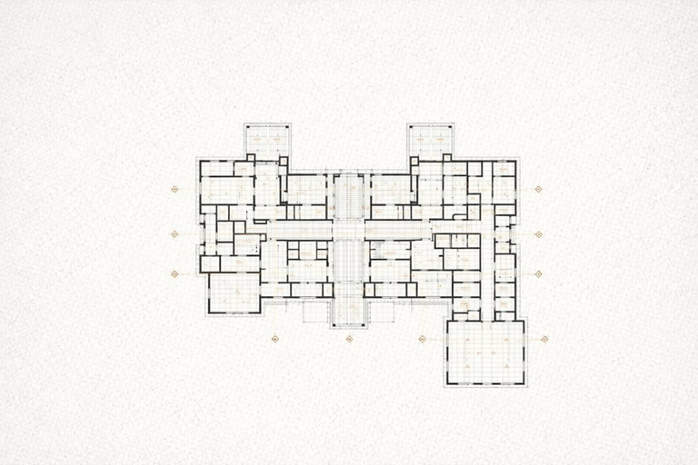
Schematic floor plans show every floor with its rooms at approximate sizes, their names and how they connect, often with the structural grid, key and overall dimensions and an area summary. The Missouri deliverables list adds accessibility routes, solar orientation diagrams and sketches of the alternatives considered. Short notes explain assumptions and design logic, which makes feedback more focused. To draw them quickly, ArchiVinci’s free floor plan maker lets you draw walls and rooms that show their area as you go and add floors, doors, windows and dimension lines; for one credit, its AI can also read a hand sketch, a plan image or a PDF into an editable plan that you then check and adjust.
Schematic Sections and Elevations
A few sections and the main elevations show heights, floor-to-floor dimensions, how the building meets the ground and its overall proportions. They stay schematic: the RAIC describes vertical sections that depict building height and outline elevations that show massing and image, and the Missouri list asks for the major sections and elevations with floor and roof lines and the main materials; detailed construction drawings come later.
Massing Models and Concept Images
Simple digital models are common at this stage: a massing model shows height, scale and volume without facade detail, so the team can judge form and site impact. Concept images and perspectives help the client picture the design, but the RAIC advises keeping them at a concept level so they do not suggest a finished product. For a first image, AI sketch to render turns a hand sketch into a photorealistic concept image, and an AI render from a 3D model view does the same with a massing screenshot, both in seconds. Every run draws a new image that follows yours, so present the results as options; using them for client work needs an active ArchiVinci plan.
Schematic Design Deliverables Checklist
Deliverables in this phase focus on clarity rather than precision. They communicate the overall design intent without defining technical or construction details. This approach keeps ideas flexible and open to revision.
Typical schematic design deliverables include:
Concept diagrams that communicate the core design idea
Preliminary floor plans showing approximate layouts and spatial relationships
Schematic sections and elevations illustrating overall proportions and vertical organization
3D massing models used to study volume, scale, and context
Outline specifications describing general material and system intentions
Preliminary cost estimation based on early area and volume studies
Basic BIM modeling files representing the project at a conceptual level
The checklist below shows what each deliverable usually covers at schematic design level and which of the sources in this guide names it. Your contract or the owner’s design manual sets the exact list.
Deliverable | What it shows at SD level | Source |
|---|---|---|
Bubble or adjacency diagrams | Spaces, relative sizes, adjacencies and circulation | RAIC (functional block plans) |
Site plan | Building location, access, parking, setbacks and site circulation | AIA, RAIC, Missouri |
Floor plans of all levels | Rooms with names and approximate sizes, structural grid, key dimensions | AIA, Missouri |
Area summary | Room areas and a gross-to-net area tabulation | Missouri, RAIC |
Sections and elevations | Heights, floor lines, massing and main materials | AIA, RAIC, Missouri |
Massing models and concept images | Volume, scale and context, kept at a concept level | AIA, RAIC |
Structural and MEP narratives | Proposed systems, design criteria, space for shafts and plant rooms | Missouri, DASNY, RAIC |
Code overview | Occupancy, egress, accessibility and zoning limits | Missouri, DASNY, RAIC |
Outline specification | Main materials and building systems | Missouri, RIBA Stage 2 |
Cost estimate | Area-based or major-component estimate, compared with the budget | AIA, RAIC, Missouri |
Schematic design report | Design approach, fit with the brief, cost, schedule and code status | RAIC, Missouri |
Make your schematic floor plans in the browser Start from a sketch, a plan image or PDF, or a short brief, or draw from scratch: you get an editable plan with room names and areas on several floors, a 3D and massing view and DXF export for your CAD program. Drawing is free; AI reading of a sketch or plan costs a free account 1 credit, and a new account starts with 3 free credits. Best on desktop. |
How Does Schematic Design Fit Into the Architectural Process?
Schematic design sits between programming and design development. Programming defines project needs and goals, while later phases define technical solutions. Schematic design connects these steps by turning requirements into a clear concept.
Schematic design also prepares the project for the next phase. Once the concept is approved, design development can focus on detail and coordination. In short, it acts as the bridge between ideas and execution.
Schematic Design vs. Concept Design vs. Design Development
The names depend on the framework. In the AIA’s standard agreement there is no separate concept phase: basic services start with schematic design. The RIBA calls its matching stage Concept Design (Stage 2), so in the UK the two terms describe the same stage. In Australia, NATSPEC lists Concept Design and Schematic Design as two stages, one after the other. In each case, design development or its equivalent comes next. The table compares schematic design with design development:
| Schematic design (SD) | Design development (DD) |
|---|---|---|
Main question | What will be built: layout, size and form | How it will be built: systems, materials and coordination |
Drawings | Site plan, schematic plans, a few sections and elevations, diagrams and massing | More precise, coordinated plans, sections and elevations |
Dimensions | Approximate sizes; key and overall dimensions | Dimensioned and coordinated with the engineers |
Engineering | Structural and MEP concepts and narratives | Systems developed and coordinated in more detail |
Cost estimate | Class 4: about −20 % to +30 % | Class 3: about −15 % to +20 % |
Approval | The client approves one direction, ideally in writing | Builds on the approved schematic design |
AIA and RIBA names | Schematic Design; RIBA Stage 2, Concept Design | Design Development; RIBA Stage 3, Spatial Coordination |
Schematic Design in the AIA, RIBA and Other Plans of Work
Each country or institute divides design into its own stages, so the same work can carry a different name. The table shows where schematic design sits:
Framework | Stages around schematic design | What to know |
|---|---|---|
AIA B101-2017 (USA) | Schematic Design → Design Development → Construction Documents → Procurement → Construction | SD is the first of five phases of basic services; programming and site feasibility are separate services |
RIBA Plan of Work 2020 (UK) | Stage 1 Preparation and Briefing → Stage 2 Concept Design → Stage 3 Spatial Coordination → Stage 4 Technical Design | The RIBA’s own comparison puts Stage 2 beside the AIA’s schematic design; a planning application generally follows Stage 3 |
RAIC (Canada) | Pre-design → Schematic Design → Design Development | Formal written approval of the schematic design before design development |
NATSPEC (Australia) | Concept Design → Schematic Design → Design Development → Contract Documentation | Concept design and schematic design are two separate stages |
Spain (Royal Decree 2512/1977) | Estudio previo → Anteproyecto → Proyecto básico → Proyecto de ejecución | The anteproyecto is the closest match: plans, elevations and sections to scale without dimensions, and an early budget; the proyecto básico is used to apply for the building permit |
Italy, public works (D.Lgs. 36/2023) | Progetto di fattibilità tecnico-economica (PFTE) → Progetto esecutivo | The law sets two design levels and names no separate schematic phase |
Sources: the AIA B101-2017 summary, the RIBA Plan of Work 2020 and its overview (NATSPEC appears in its comparison of international plans of work), RAIC chapter 6.2, Spain’s Royal Decree 2512/1977 and Italy’s Legislative Decree 36/2023, article 41.
Budget and Cost Estimates in Schematic Design
Financial limits shape design decisions from the very beginning. Architects work closely with cost consultants to develop preliminary cost estimates that reflect early design intent. These estimates typically rely on area calculations, system assumptions, and initial structural concepts.
How accurate is such an estimate? Under the ASTM E2516 classification, which the Government of Alberta adopts in its guide to classes of construction cost estimates, a schematic design estimate is Class 4: it rests on about 1 to 15 % of the project’s definition, uses parametric or functional-space pricing and has a typical accuracy of about −20 % to +30 %. A design development estimate (Class 3) narrows that to about −15 % to +20 %. The guide adds that the ranges overlap between projects, so every estimate should state its limits and contingencies.
When projected costs exceed the available budget, teams apply value engineering strategies. This process adjusts materials, systems, or spatial priorities while preserving core performance goals. In parallel, risk assessment helps identify potential financial and technical uncertainties early.
Common Challenges in the Schematic Design Phase
Although this phase allows exploration, it also introduces several practical challenges. Architects must balance creative ideas with real constraints while decisions are still fluid.
Therefore, clear priorities and structured feedback become essential.
Managing scope as ideas develop, ensuring exploration does not expand beyond project goals
Aligning budget expectations with spatial ambition, so early concepts remain financially realistic
Interpreting unclear or changing client input, which can shift priorities during concept formation
Addressing site and zoning limitations early, before they restrict later design options
Client Collaboration and Decision Making in Schematic Design
Client involvement strongly influences the direction of the project. Architects organize workshops and design charrettes to refine goals, priorities, and spatial needs. Regular stakeholder meetings help clarify expectations, constraints, and success criteria.
Iterative feedback loops allow the design to evolve before formal approvals. Decision checkpoints confirm alignment with scope, budget, and regulatory requirements. As a result, strong collaboration reduces misunderstandings and increases confidence in the final concept.
During this phase, responsibilities remain clearly defined. Client feedback focuses on goals, priorities, and spatial needs. Consultant input, such as structural, MEP, or cost advice, supports feasibility and coordination. Internal design decisions remain with the architectural team, ensuring concept consistency and design integrity.
Schematic Design Approval Criteria
Schematic design approval confirms that the project is ready to move forward. Approval is typically based on alignment across several key areas rather than design detail.
Client approval, confirming that the concept meets functional, spatial, and aesthetic expectations
Budget alignment confirmation, verifying that preliminary cost estimates fit financial limits
Regulatory feasibility confirmation, ensuring zoning, codes, and planning constraints are addressed
No unresolved adjacencies: the RIBA advises against moving to the next stage while spatial requirements or room adjacencies remain inconclusive
Written sign-off: the RAIC recommends formal written approval of the schematic design before design development begins
Once these criteria are met, the project can progress confidently into design development.
Transition to Design Development After Schematic Design
Once schematic design receives approval, the project moves into design development. Architects begin refining materials, facade systems, and technical components in greater detail. Preliminary drawings evolve into coordinated and more precise documentation. If you drew the schematic plans in ArchiVinci’s free floor plan creator, you can export them as DXF, which AutoCAD and other CAD programs open and can save as DWG, so the approved plans become the base of the design development drawings.
This transition marks a shift from exploration to technical definition. Early design decisions continue to guide the project while engineering integration becomes more detailed and exact.
A Schematic Design Example: A Two-Story House
Here is how the phase can run on a simple project: a client wants a three-bedroom family house on two floors, about 180 m² (about 1,940 sq ft), on a suburban lot. The steps follow the tasks described above; the tools are examples, not requirements.
Brief and site: confirm the rooms, the target area, the budget and the schedule, and note the lot’s setbacks, height limit, access and orientation.
Layout options: sketch two or three bubble diagrams, or enter the program in the brief generator of Floor Plan Maker (property type, total area, floors, bedrooms, bathrooms), which builds a furnished layout from it without AI and at no cost; “Try another layout” gives a new variation to compare.
Schematic plans: develop the chosen option into plans of both floors with room names, areas, the stair opening and the main dimensions; code and egress checks stay with you.
Massing and review: look at the volume in a 3D massing view, change the sun direction for a quick visual check (not a sun-path study), and walk through the rooms in first person with the client.
Concept image: render the 3D view as an exterior scene in Floor Plan Maker, which uses ArchiVinci’s render engines and credits, or upload a sketch to an AI render tool, and discuss materials and light with the client; show the image as an option, and remember that client work with AI renders needs an active plan.
Sections and elevations: draw one or two sections and the main elevations in your CAD or BIM program, starting from the plan exported as DXF, since Floor Plan Maker does not draw sections or elevations.
Estimate: use the room areas from the plans with your cost consultant’s unit costs to prepare a Class 4 estimate, and compare it with the budget.
Sign-off: present the set with a short report and get the client’s written approval before design development begins.
Digital Tools Used in Schematic Design
Technology improves both speed and decision quality during early design stages. Architects rely on digital tools to explore form, test assumptions, and communicate ideas clearly. Therefore, schematic design benefits from faster iteration and more informed choices.
Parametric modeling tools allow architects to test building form variations efficiently. Environmental simulation software supports early sustainability checks, such as daylight, solar exposure, or energy demand. These insights guide decisions before technical constraints increase.
Common tools include:
BIM platforms, such as Revit and Archicad, used for spatial layouts and basic building data; our guide to BIM software compares the main options
Parametric design software, including Grasshopper, the graphical algorithm editor included with Rhino, which enables rapid form and logic exploration
Energy analysis applications, like Ladybug Tools, a free set of environmental design tools, or Sefaira, which Trimble presents for concept and schematic design, supporting early environmental performance studies
3D modeling tools, such as SketchUp, used for quick massing models; our list of 3D modeling software covers more options
Real-time visualization tools, such as Enscape, now part of Chaos, and Lumion, which render views of a CAD or BIM model to show early ideas for feedback
Browser floor plan tools, such as ArchiVinci’s own Floor Plan Maker, for schematic plans with room areas on several floors, 3D and massing views, and export to DXF, SVG, PDF, PNG, GLB and OBJ, in desktop browsers
AI image tools, such as ArchiVinci’s AI rendering, which turns a sketch or a massing screenshot into a photorealistic concept image that follows it, in seconds
Key Takeaways
Schematic design sets the foundation of the architectural design process by defining concept, layout, and overall direction early.
It focuses on design intent rather than technical detail, allowing flexibility and iteration before decisions become fixed.
Client requirements are translated into conceptual strategies and preliminary drawings that guide the project forward.
Site analysis and zoning review, built on earlier feasibility studies, ensure early regulatory and contextual alignment.
Massing studies and space planning shape building form, layout, and spatial relationships.
Early attention to budget control and value engineering supports financial feasibility.
Structural and MEP coordination at a conceptual level reduces technical risks later.
Digital tools and BIM workflows improve iteration speed, collaboration, and clarity.
Strong schematic planning improves coordination, cost control, schedule reliability, and long term project quality.
Try it in ArchiVinci
Describe a building in a sentence, or upload a sketch or a 3D model view: ArchiVinci generates concept images that follow it. A new account starts with 3 free credits.
For early design concepts: AI concept generator
For architecture concepts: AI architecture generator
Frequently Asked Questions
How does schematic design differ from design development?
Schematic design focuses on defining the overall concept, massing, and spatial layout. Design development refines these ideas by adding technical systems, material decisions, and coordinated drawings. In short, the process moves from exploration to technical definition.
What is the difference between concept design and schematic design?
It depends on the framework. For the RIBA, Concept Design (Stage 2) is the stage that matches schematic design, while the AIA’s standard agreement starts directly with schematic design. In Australia, NATSPEC lists them as two stages, with concept design first and schematic design second.
What comes after schematic design?
Design development. In the AIA’s B101 agreement, schematic design is followed by design development, construction documents, procurement and construction. In the RIBA Plan of Work 2020, Stage 2 Concept Design is followed by Stage 3 Spatial Coordination and Stage 4 Technical Design.
What are the phases of architectural design?
There is no single standard. The AIA’s B101 agreement has five phases of basic services: schematic design, design development, construction documents, procurement and construction. The RIBA Plan of Work 2020 has eight stages, numbered 0 to 7, from Strategic Definition to Use. Lists of seven stages found online are not a standard, so check which framework your contract follows.
How long does schematic design usually take?
It depends on the size and complexity of the project, how many options the client wants to compare and how quickly decisions are made. No standard sets a duration, so the schedule is agreed in each contract; small, simple projects usually move faster than large ones with many stakeholders.
Is schematic design required for every architecture project?
Most professional projects include schematic design as a defined phase. However, very small or repetitive projects may combine it with later stages: the AIA’s abbreviated agreement for projects of limited scope, B104-2017, has three phases (design, construction documents and construction) instead of five.
Does schematic design include structural calculations?
Schematic design does not include detailed structural calculations. It relies on high level assumptions that are refined during design development, although some public owners already ask for typical bay and member sizes and a short structural narrative at this stage, as the Missouri Office of Administration’s list does.
Can changes still be made after schematic design approval?
Yes, changes are still possible after approval. However, they become more time consuming and costly as the project progresses.
Are materials selected during schematic design?
Materials are considered only at a conceptual level. Final selections and specifications are developed in later phases.
How detailed are schematic floor plans?
Schematic floor plans show approximate room sizes, adjacencies and circulation, often with room names, key and overall dimensions and an area summary. They do not include full construction dimensions or details.
How accurate are cost estimates at the schematic design stage?
Cost estimates are preliminary and based on area calculations or comparable projects. Under the ASTM classification that the Government of Alberta’s guide uses, a schematic design estimate is Class 4, with a typical accuracy of about −20 % to +30 %; accuracy improves as design decisions become more defined.
Is schematic design 30 % of the design?
Not as a rule. The percentage is a review milestone that each owner sets, not a standard and not a fee share. The Dormitory Authority of the State of New York (DASNY) calls its schematic design submission the “30% submission”, the Missouri Office of Administration describes the phase as about 20 % of design, and the Iowa Army National Guard’s schematic submittal is its 10 % submission. Check your contract or the owner’s design manual for the milestone that applies.
Who is typically involved during schematic design?
The architect and client are always involved. Consultants such as structural or MEP engineers may provide early input when required.
What documents are usually delivered at the end of schematic design?
Deliverables typically include concept diagrams, schematic plans, massing studies, and preliminary cost estimates. These documents support client approval.
What decisions are confirmed after schematic design approval?
The overall design direction, spatial layout, and building massing are confirmed. These decisions guide all later technical development.
How does zoning impact schematic design decisions?
Zoning regulations influence height, setbacks, density, and allowable uses. Addressing them early prevents major redesign later.